Setting Waveform Parameters
Setting Waveform Parameters
Waveform generator block diagram

* Waveform generator (generator)
- There are Wave 1 ~ Wave 8 waveform generators, and you can mix and output each waveform output.
- I have another pair of Wave 1 ~ Wave 3 up to V1.40 plus Wave 4.
That is, Wave 1 and Wave 5, and Wave 2, 3, 4 and Wave 6, 7 and 8 are the same except for some.
For Wave 1 and Wave 5, a band limitation waveform generation function not included in V 1.40 has been added.
Wave 1 to 4 and Wave 5 to 8 are tabs You can switch with.
The tab of the currently effective one is highlighted (the color changes), but the display of 1 to 4 and 5 to 8 are displayed in Wave 1 Please be aware that it is the same except that there is a button.
 - Besides this, oversampling and filtering with arbitrary characteristics can be multiplied and output.
Detail is Output filter Please refer to.
* It is the setting group box of Wave 1 on behalf of
If you click the position of a figure button, combo box, etc., it jumps to the explanation of that part.

==== Wave 1 ~ Wave 8 common specification ====
- Waveform

If OFF: OFF , the function stops and becomes invalid regardless of other Wave settings. (From V1.50)
So it is a good idea to set OFF for unnecessary Wave. (Useless CPU load can be reduced)
periodic waveform: sine wave , square wave , triangle wave , sawtooth wave , pulse , pulse (+ -) .
Pulse (+ -) generates positive and negative alternating pulse trains. (From V1.50)
Noise: White Noise , Pink Noise , M Series Noise
* Note that the triangle wave and the sawtooth wave are consistent with the band limit waveform (see the function of only Wave 1 and Wave 5 - band limitation ) Therefore, the starting point of the waveform has been changed as follows. (Start from the negative maximum value)
|
|
V1.40 |
|
V1.50 |
|
|
triangle wave |
|
-> > |
|
phase difference |
|
sawtooth wave |
|
-> > |
|
phase difference |
- frequency / period

When the unit is Hz , the frequency is set as it is, and when the unit is Sa , it is set as the cycle according to the number of samples.
You can set it to an arbitrary value by selecting the preset value in the combo box or by directly writing the value.
If the set frequency exceeds 1/2 of the sampling frequency, the background of each combo box becomes "red" and warns you.
In this case, the signal is generated without errors in particular. Although it does not become a correct signal with what is called "return", it can be used for purposes that make it on purpose after returning.
(No wrapping signal will be output if band limitation is set to anything other than " no " at Wave 1 or Wave 5)
* Unit setting / modification
Right clicking on the unit part such as Hz on the right of the frequency / cycle combo box will pop up a pop-up menu, so set it there.

Instead of right-clicking, you can also change the order by left-clicking on the unit part.
If you change the unit, the previous value will be converted and displayed in the new unit.
(Even if you set it in any unit, it is the same internally.)
* Frequency setting extension
There is an extension function for special frequency setting.
See Frequency setting extension for details.
- Amplitude

When the unit is dB , when the maximum is 0 decibel value (negative) and the unit is value , it is directly up to 32767 (when 16 bits or more), or 127 (When 8 bit), and when the unit is % , it will be set with a maximum of 100 percentage value.
* However, this is the maximum value as a PCM signal, which is usually set as a reference value for clarity if you set it more than this, but the output filter It is also possible to set a value (positive) of 0 dB or more so that it can be amplified when it is known that the amplitude becomes obviously small, such as when multiplied. (V1.50 From Please check the level display and set it.
By selecting the preset value in the combo box or by directly writing the value arbitrary value can be set.
* Setting / changing units
Right clicking on the unit part such as dB on the right of the amplitude combo box will pop up a pop-up menu and set it there.

Instead of right-clicking, you can also change the order by left-clicking on the unit part.
If you change the unit, the previous value will be converted and displayed in the new unit.
(Even if you set it in any unit, it is the same internally.)
When amplitude is input when the unit is value , you can also enter it in hexadecimal by adding "0x" before the numerical value.
Also, as you can see at the time of conversion from others, it is not necessary to be an integer.
(The same is true for hexadecimal numbers)
Note: When bit length of Wave format is switched, when the unit is dB and%, it is automatically converted to the maximum possible value internally, but when the unit setting is the value, the automatic conversion is It will not be done. Therefore, when changing from 8 bit to 16 bit, the sound becomes smaller, and there is a possibility of level over in 16 bit → 8 bit.
Note: For 24, 32 bit format
Actually outputted values are integers up to 2 ^ 23 - 1, 2 ^ 31 - 1 respectively, but for the sake of compatibility and ease of setup up to now, unit setting is value At the time of, the numerical value set in the combo box is 32767 in all cases as well as 16 bit.
(It's usually easier to set it with dB or % )
- Offset

Specifies the offset (DC component) to add to the waveform.
The specification method is exactly the same as the amplitude.
Note:
Even if the waveform is OFF (invalid) only when using this wave as a modulation signal, only this offset is effective as an internal signal and can be used as a modulation signal.
(Output is not done regardless of the output channel setting.) - output channel

Set the channel to output the signal generated by this wave.
In Stereo (Mono), both channels are output by L + R , left channel by L , only to right channel by R I will.
In the case of multi channel with 3ch or more, ALL on all channels, 1 ch , 2 ch , 3 ch ... It is output to each channel only.
OFF: OFF will not output anywhere.
==== Wave 1 and Wave 5 only features ====
- User Waveform
Wave 1 and Wave 5 can also generate and generate arbitrary waveforms (Wave format and original text format) as user waveforms.
For details, please refer to How to use user waveform . - Bandwidth limit
In the periodic waveforms of Wave 1 and Wave 5, it is possible to generate a periodic waveform with band limit without alias distortion.
See Bandwidth Limit for details. - Smooth change in frequency / cycle and amplitude (volume) with mouse wheel
Using the Sweep function of Wave 1 and Wave 5, it became possible to smoothly and continuously change the frequency and amplitude (volume) with the mouse wheel, and it approached the operability of the analog oscillator. (V1.50 From
With the mouse cursor on the frequency / period combo box of Wave 1 or Wave 5 and turning the mouse wheel , Frequency, or period, and you can change the volume by rotating the mouse wheel over the amplitude combo box
  I will.
To be exact, the mouse wheel will operate on the up / down control on the right of each combo box as well.
* For these mouse wheel operations, press the up and down buttons of each up / down control Please note that it is exactly the same.
The change amount and change time when turning the mouse wheel can be changed by each up / down control setting.
For details, refer to the following up / down control section. - Frequency / period
 Up Down control
For Wave 1 and Wave 5, you can also change the value with the up / down control to the right of the frequency / period combo box.
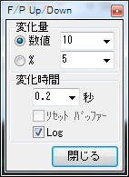
You can freely change the amount of change and change time in the dialog displayed by right-clicking the mouse on the up / down control.

- Change amount
You can change it with number or % .
Set the change amount to arbitrary value by selecting the preset value in the combo box or by directly writing the value You can do.
For example, if the unit is frequency, % and setting the value to 5.94630943592953 (the second root of 2), you can change it semitone by semitone.
Note: If you change 1000 Hz by%, if it is up by 10% It becomes 110% of 1100 Hz, but in case of down 90% not 900 Hz, 1000 / 1.1 909.090909090909 Hz Please be careful.
It will be calculated up / down and back. - Change time
The change time is the time to change the change amount of the above, and it can set an arbitrary value (up to 100 seconds).
If the change time is set to something other than 0, it multiplies that time and makes a continuous change like a sweep.
If the change time is set to 0, continuous change does not occur and it becomes step operation.
Also check the Reset buffer checkbox, which will be enabled at that time, so that the buffer will be cleared every time it changes and will change after a moment of interruption. (It works the same as V 1.40.)
If you want to change while keeping the phase relation between each wave, it is good to set like this.
The way of change is Log (logarithmic) if the Log checkbox is checked when the change time is not 0, it changes linearly if it is not checked.
However, at the time of setting a general small change rate, neither should be particularly different.
It is effective when setting a bigger change as shown below.
For example, when the current oscillation frequency is 20 Hz, setting the change amount to 19980 and the change time to 60 seconds and pressing the up button once takes 60 seconds It will sweep from 20 to 20000 Hz.
Linear sweeping is also possible with Log / Linear setting at this time.
Sweep operation is possible even if it is not the original sweep setting (described later). - Frequency setting bar
Frequency setting bar button to the right of Wave 1 only, frequency / period combo box
 to open the frequency setting bar window to change or sweep You can also do.
Furthermore, it is possible to change the frequency of Wave 5 synchronously at an arbitrary ratio.
See frequency setting bar for details. - Amplitude
 Up Down Control
For Wave 1 and Wave 5, you can also change the value with the up / down control on the right of the amplitude combo box.
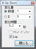
Change amount and change time can be freely changed in the dialog displayed by right clicking the mouse on the up / down control.

Usage is the same as above frequency / cycle.
- Number of delay samples

You can delay the occurrence of Wave 1 and Wave 5 from the others by the set number of samples.
(The waveform is shifted to the right by the number of samples, and the value of the waveform in the delayed part is all zero.)
You can set arbitrary value by choosing a preset value in the combo box or writing a direct value . - Phase

Advance the phases of Wave 1 and Wave 5 from the others by the set frequency (0 to 360°).
(The waveform shifts to the left by that amount)
You can set arbitrary value by choosing a preset value in the combo box or writing a direct value .
These two are valid only with periodic waveforms (sine wave, rectangular wave, triangular wave, sawtooth wave, pulse, pulse (+ -)). - sweep

By checking this check box you can activate the sweep function.
Three of frequency, amplitude, and phase can be swept at the same time, but
For Wave 1: Wave 1 setting is initial value , Wave 2 setting is final value
Wave 5 setting is initial value, Wave 6 setting is final value for Wave 5:
.
For example, if the frequency of Wave 1 is 100 Hz amplitude -10 dB, Wave 2 If the frequency is 1000 Hz and the amplitude is 0 dB, the sound changes from 100 Hz to 1000 Hz as the sound increases.
(Therefore, please set the same settings for Wave 1 and Wave 2, or Wave 5 and Wave 6 for objects that you do not want to change in reverse)
* Final Values For Wave 2 and Wave 6 settings, only the frequency and amplitude values are used, the rest are irrelevant to the sweep operation itself.
So if you do not need it, you can leave the waveform OFF .
Actually when you want to use the waveform of Wave 2, Wave 6 Please enable and set the output destination.
Sweep time (seconds), " Wave file length / Sweep length " Specify by combo box.
(Even when outputting to a sound device that normally does not stop until you press the stop button, the sound will stop after sweeping at the set time here.)
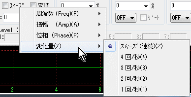
How to change the sweep (linear, Log, continuous change, step change) are set in the popup menu displayed by right-clicking the mouse on the check box.

* There is no Wave 2 or Wave 6 setting for only the phase, so the final value is also set in the popup menu.
(Value of Wave 1 -> 360° or Wave 1 value - > 0°)
(Wave 5 value -> 360° or Wave 5 value -> 0°)
Also, the phase change is linear only.
* It is also possible to reduce the value of Wave 2 (Wave 6) rather than Wave 1 (Wave 5) in the frequency and amplitude, and change it in the opposite direction.
* Even sweeping of the amplitude is possible even in the case of white noise, pink noise, M series noise.
Since the user's waveform is handled differently from others, it can not be swept.
- Modulation

If you select this check box, you can activate the modulation function.
The modulation wave (modulation signal) is fixed at Wave 3 or Wave 5 in Wave 1, and Wave 7 in Wave 5.
(In V 1.40, the modulation wave of Wave 1 was Lch output of Wave 3, but it was changed.)
* When Wave 5 uses a user waveform as the modulation signal of Wave 1, it is possible to select a signal to be used as a modulation signal separately from the normal output destination selection.
See user waveform for details.
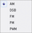
The type of modulation (AM, DSB, FM, PM, PWM) is set in the popup menu displayed by right-clicking the mouse on the check box. (PWM From V1.50)
In Wave 1, Wave 3 or Wave 5 can be selected with the lowest " modulation signal ".
 when Wave 1
  When it is Wave 5
AM (Amplitude Modulation Amplitude Modulation)
When the amplitude of the modulated wave (Wave 3/5 or Wave 7) is set to 100%, the degree of modulation of the carrier wave (carrier Wave 1 or Wave 5) is 100% .
For example, if the amplitude of the carrier wave Wave 1 is set to 50% and the amplitude of the modulation wave Wave 3 is set to 100%, the peak of the output becomes the maximum amplitude (0 dB).
DSB (Double Side Band Carrier Suppression Both Sideband Amplitude Modulation)
When the amplitude of the modulated wave (Wave 3/5 or Wave 7) is set to 100%, the degree of modulation of the carrier wave (carrier Wave 1 or Wave 5) is 100% .
For example, if the amplitude of the carrier wave Wave 1 is set to 100% and the amplitude of the modulation wave Wave 3 is set to 100%, the peak of the output becomes the maximum amplitude (0 dB).
* Mathematically it is a product of the carrier wave and the modulation wave, so when the amplitude of the modulated wave is 0%, the output also becomes zero.
FM (Frequency Modulation Frequency Modulation)
When the amplitude of the modulation wave (Wave 3/5 or Wave 7) is set to 100%, the frequency deviation of the carrier wave (carrier Wave 1 or Wave 5) is ± 100%.
For example, if setting the frequency of the carrier wave Wave 1 to 1000 Hz and setting the amplitude of the modulation wave Wave 3 to 100%, the output frequency changes from zero (direct current) to 2000 Hz.
PM (Phase Modulation Phase Modulation)
When the amplitude of the modulation wave (Wave 3/5 or Wave 7) is set to 100%, the phase shift of the carrier wave (carrier Wave 1 or Wave 5) is ± 360 °.
PWM (Pulse Width Modulation Pulse Width Modulation)
When the amplitude of the modulated wave (Wave 3/5 or Wave 7) is changed from the positive maximum value to the negative maximum value, the duty cycle (duty ratio) of the carrier wave (carrier Wave 1 or Wave 5) It will be 100% ~ 0%.
Actually, however, it is limited to 99% to 1%.
When the modulation wave has zero DC level, the duty cycle of the carrier wave is 50%.
The relationship between the modulation wave amplitude (DC level) or offset and duty cycle is as follows.
|
amplitude |
+100% |
+98% |
+96% |
+90% |
+80% |
+70% |
+60% |
+50% |
+40% |
+30% |
+20% |
+10% |
0 |
|
DUTY |
(99%) |
99% |
98% |
95% |
90% |
85% |
80% |
75% |
70% |
65% |
60% |
55% |
50% |
DUTY = amplitude / 2 + 50 [%]
|
amplitude |
0 |
-10% |
-20% |
-30% |
-40% |
-50% |
-60% |
-70% |
-80% |
-90% |
-96% |
-98% |
-100% |
|
DUTY |
50% |
45% |
40% |
35% |
30% |
25% |
20% |
15% |
10% |
5% |
2% |
1% |
(1%) |
*The signal that can be used as a carrier wave is a periodic waveform (rectangular wave, triangular wave, sawtooth wave, pulse, pulse (+ -)) other than sine wave. (However, it is not possible to change the duty cycle of the band limit waveform by addition synthesis.)
* When the number of samples of the cycle of the carrier wave is small (frequency is high), the setting of the duty cycle becomes difficult to reflect, as a matter of course.
(To set it to 1 or 99, it will naturally not be reflected unless the period is 100 or more)
Carrier limit
There are no restrictions other than white noise, pink noise, M series noise, user waveform in the FM, PM and PWM carrier types can not be used for carrier type.
There is no limitation on the type of modulation wave (Wave 3/5 or Wave 7) at all.
* Therefore, if AM, DSB, it is also possible to modulate the user waveform of Wave 1 with the wave form of Wave 5.
Modulation wave
The signal used as a modulation wave is the internal output of Wave 3/5 or Wave 7, not related to each output setting.
Therefore, you can leave the output channel setting OFF when there is no need to output.
Conversely, if you want to use it, you can set the output.
(The output of Wave 3 was used as a modulated wave and was not mixed as output, but it was changed up to V 1.40 when the modulation function was enabled.)
- Gate (for tone burst)

Tone burst can be output by setting optional On period (wavenumber) and Off period.
(Naturally, only the periodic waveform is the target)
Both On cycle and Off cycle can be entered in units of 0.5.
For example, if the On period is 0.5 and the Off period is 9.5, only the first half period On, followed by zero for the 9.5 period, full period A tone burst of 10 is output.
It is effective only when you set a value other than zero for both On cycle and Off cycle.
By selecting the preset value in the combo box or by directly writing the value arbitrary value can be set.
* You can control the output of Wave 2, Wave 3, Wave 4 by the gate operation of Wave 1.
* You can control the output of Wave 6, Wave 7, Wave 8 by the gate operation of Wave 5.
See below.
==== Functions of Wave 2, 3, 4 or Wave 6, 7, 8 only ====
- Gate (synchronized with the gate of Wave 1 or Wave 5)

When this check box is checked, in synchronization with the gate operation in Wave 1 or Wave 5, Wave 2, 3, 4 or Wave 6, 7, 8 will also be turned on / off.
You can check only when the gate operation of Wave 1 or Wave 5 is enabled.
* In addition to using common waveforms as Wave 2, 3, 4 or Wave 6, 7, 8, you can also make pulses of the gate signal itself by turning On / Off Offset I can do it.
* All the setting functions can be changed in real time even during signal generation.
~~~~~~~~~~~~~~~~~~~~~~~~~~~~~~~~~~~~~~~~~~~~~~~~~~~~~~~ ~~~~~~~~~~~~
Depending on the setting, however, it may become invalid and can not be changed during signal generation.
Also, when parameters such as frequency are changed during operation, there may be cases where the phase between each wave is shifted or lost due to the original operation, so especially when the phase relation is important, sweep, modulation In case of, please make a change after stopping once.
Created with the Personal Edition of HelpNDoc: Free HTML Help documentation generator


